I titled this page "Solar Thermal Panel" instead of "Solar Panel" because the words "Solar Panel" normally imply the generation of electricity. The phrase "Photovoltaic Panel" is not normally used!
If you've ever left a garden hosepipe in the sun, you'll know that the water inside can get very hot indeed. Well, put simply, that's the theory behind a solar thermal panel. The sun's energy heats the water in the panel, and this heated water is then routed into the thermal store where it releases its energy for later use. It's obviously of more use during the summer months when the sunshine is more plentiful.
There are two methods of extracting the heat; either the panel (also known as a collector) is placed below the heat store - in which case a thermosyphon effect can be used to eliminate the requirement for a pump - or the collector is above the heat store, and a pump is required. Because our collector will be roof-mounted (and our 500-litre thermal store is already in place), I selected the pump option.
There are also two main types of collector; a flat plate, or evacuated tubes. Again, each has advantages and disadvantages - but the flat plate type is the only one that can be self-built without spending too much money; and this is, after all, the La Darnoire philosophy!
With regard to panel construction, readily-available metals need to be used which are good heat conductors. This usually means copper pipes, and an aluminium backing plate. Now temperatures here can go down to minus 20°C - and an exposed copper pipe in these temperatures can be a problem. So the options are to either not use copper pipes at all; completely drain the system during the winter; or use antifreeze. I opted for the antifreeze method, using the more environmentally-friendly propylene glycol (rated to minus 25°C). The liquid in the piping is circulated around with a small pump, and will get rid of its energy in the thermal store by means of a heat exchanger (simply another coil of copper pipe - see Thermal Store construction). The pipework between the panel and the thermal store would be PEX tubing; this inserts a "thermal break" so that not too much heat is lost from the thermal store by conduction. I'm sure some convection will occur because the panel will be higher than the thermal store; but this should also help prevent the panel from freezing.
As the system will be a "closed loop" (albeit not really fully sealed), an expansion tank is necessary.
Materials used were to be scrounged as much as possible, and purchased as a last resort.
Another thing to be considered is the angle of the panel relative to the horizontal, in order to collect the maximum amount of solar energy.
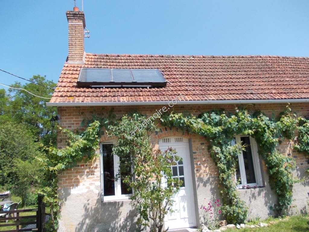
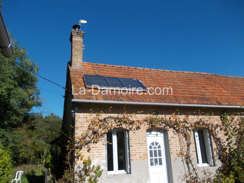
Our roof faces due south; perfect for a solar panel in the northern hemisphere. It is at an angle of 40 degrees, and our latitude is 47 degrees N. In summer, the ideal angle of a panel is 32 degrees (latitude minus 15). For winter the ideal angle is 62 degrees (latitude plus 15). It is obviously impractical to change the angle of the panel during the year, so as the easiest option I decided to simply lay it flat on the roof (i.e. at 40 degrees).
There are many different opinions on optimum angles. Ideally the panel should be at 90 degrees to the sun at all times; obviously this is impractical unless some form of solar tracking mechanism is installed. The best all-round option seems to be an angle between 35 and 45 degrees. Oh look! Our roof is at the correct angle!
So, here's how I did it:
Construction
Installation
Control Panel
Results
Costs
Construction
The first issue was to determine a suitable size for the panel. One could use something like a Campbell-Stokes recorder to determine the annual amount of sunshine in your location, and then calculate the panel size according to your heating requirements. The mathematics is quite involved. For simplicity I decided to base the panel size on the materials I had available.
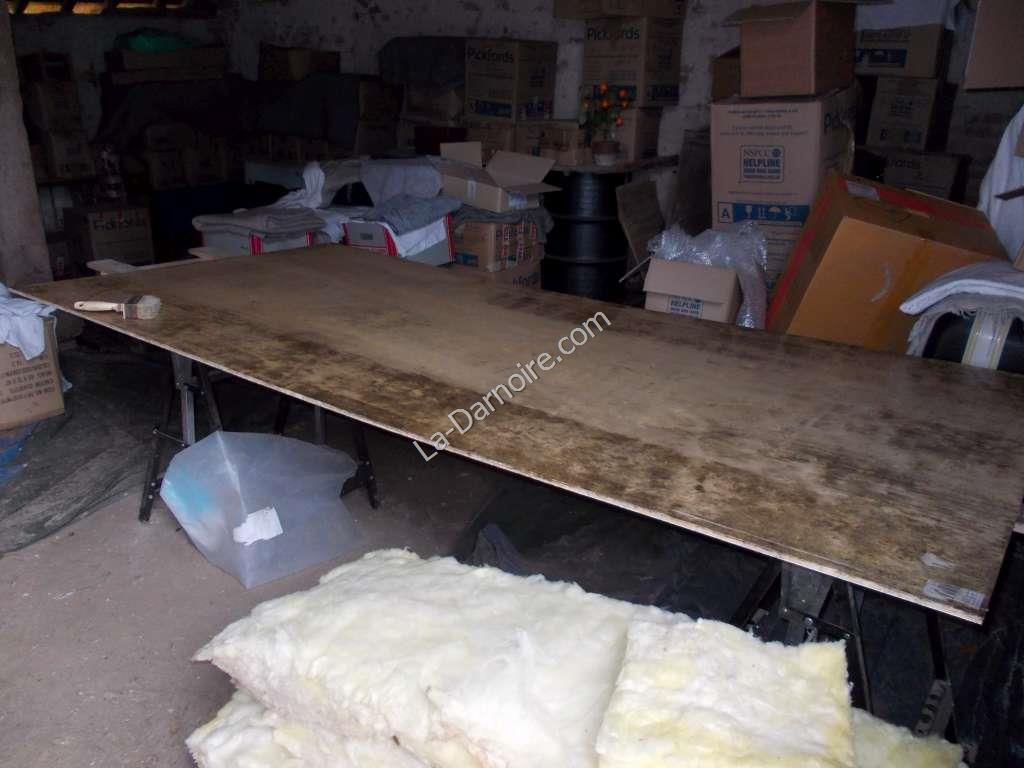
Some panes of glass had been salvaged from an old combine harvester; and as luck would have it, the three panes placed side by side measured 1200mm by 2400mm - close enough to the standard size of a sheet of plywood. This will give 2.88m2 of collector area. Having obtained the required planning permission to install the panel on our roof, I purchased two plywood sheets with a thickness of 10mm, laid the first across some trestles, and painted it on all sides with a borax solution to discourage insect activity:
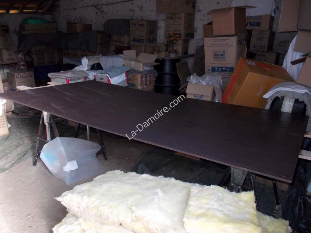
Followed by a coat of brown wood paint:
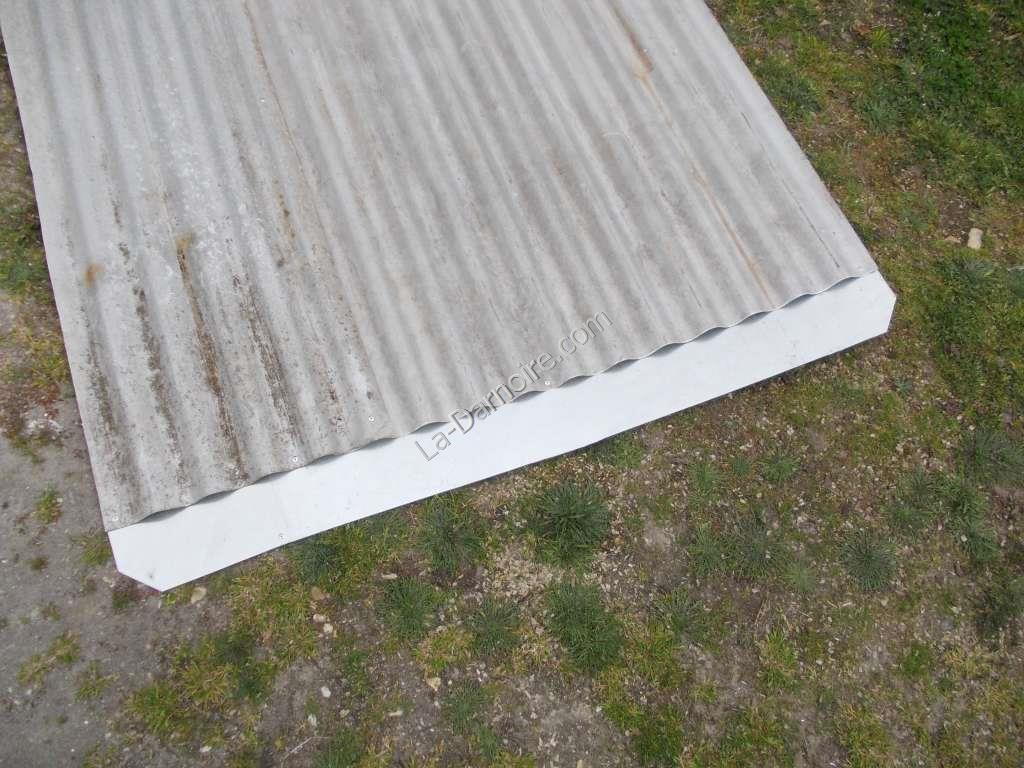
Next I re-used some corrugated iron sheets. Except they weren't corrugated iron, they were actually aluminium - which is an ideal metal to use for the base of a flat plate collector. I cut them to the correct size, joined two together with aluminium rivets, and added a piece of thin aluminium plate at each end; this plate is where the copper pipe will bend through 180°.
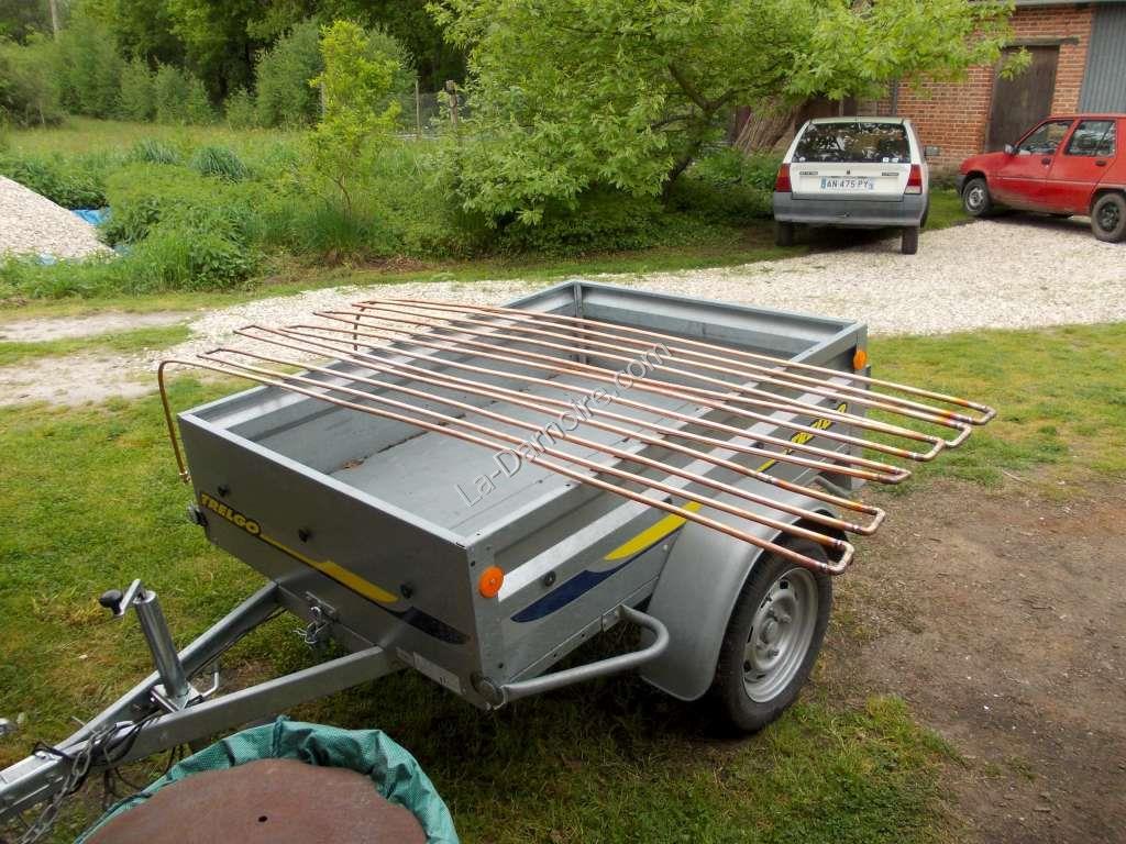
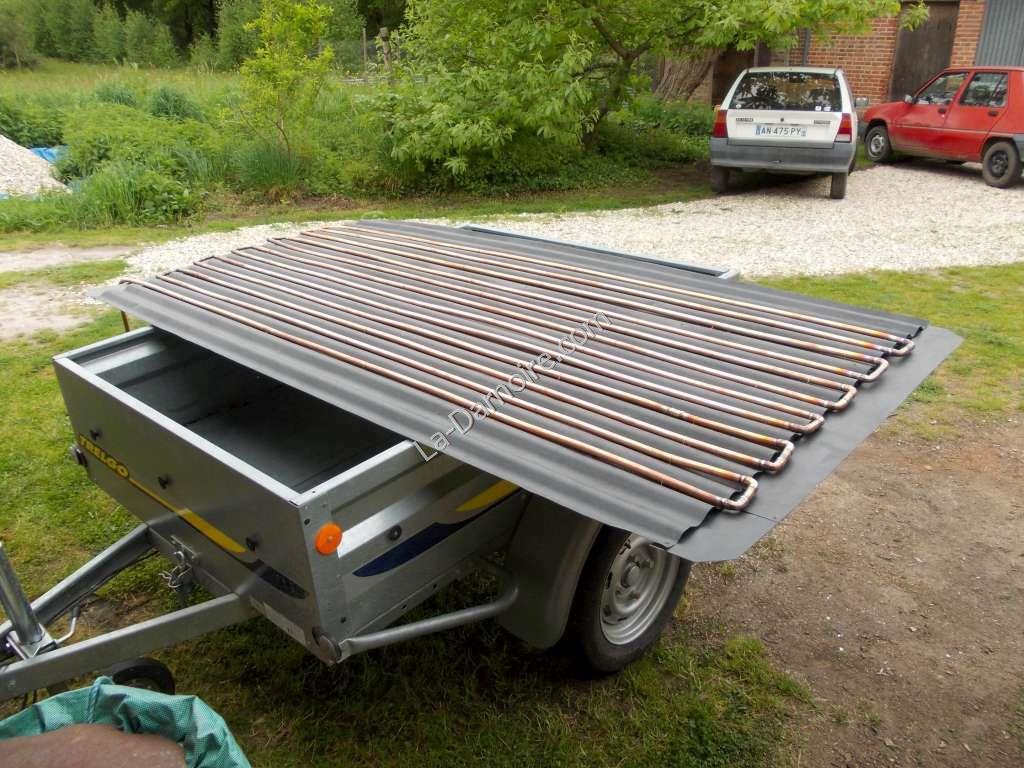
Copper tubing was now required. As I had already used 16mm diameter tubing in the thermal store and house plumbing, I decided to use this size for the panel as well. I found it difficult to make 180° bends, so instead used two pre-formed 90° bends at each end. This involved quite a bit of soldering. Once all the soldering was complete, I tested for leaks by using water at a pressure of 6 bars. It's hard to believe, but this is what 30 metres of copper tubing looks like:
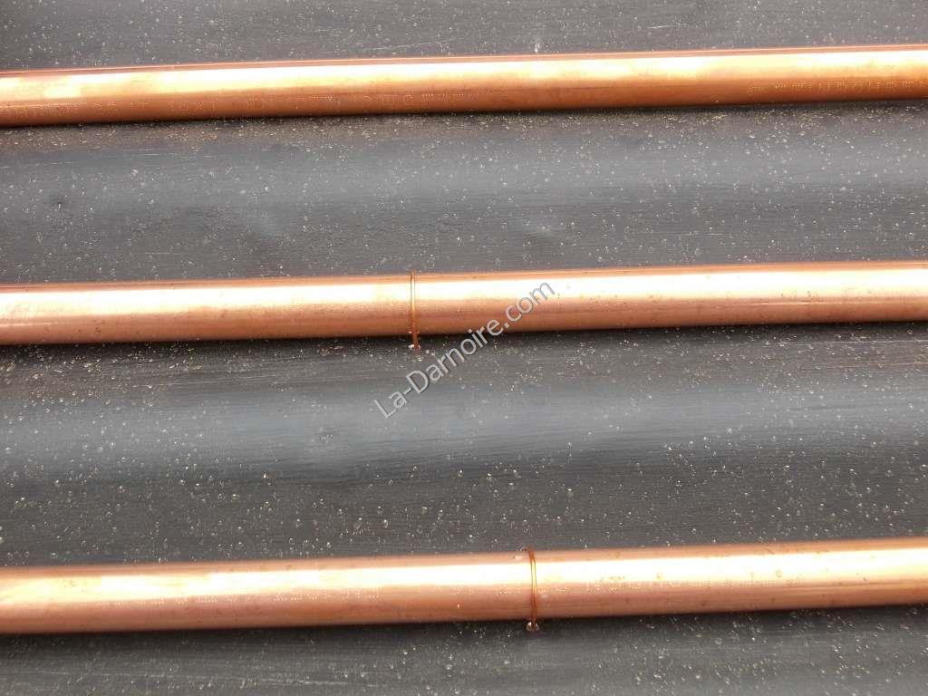
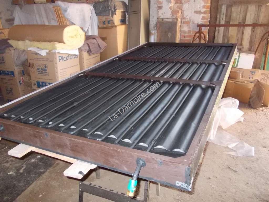
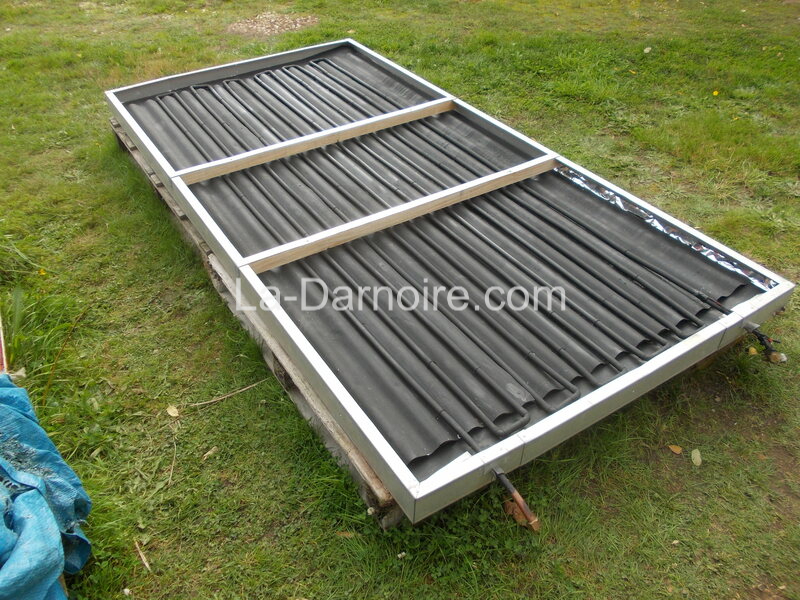
Using high temperature matt black paint, I painted the aluminium sheet, and then fixed the copper tubes in place by drilling small holes on both sides of the tube and using some re-purposed electrical wiring (which is copper as well of course!) to tie the tubes to the panel, 5 ties per tube. This ensures a good surface contact along the length of each tube.
Because I used corrugated sheet, in the next photo you can see the reasoning behind the flat plate at each end of the panel. The ends do make good contact with the plate here, but in this photo the panel is obviously unsupported at the ends so there appears to be a bit of a gap. The copper piping fits quite nicely in the "hollows" of the corrugated-aluminium!
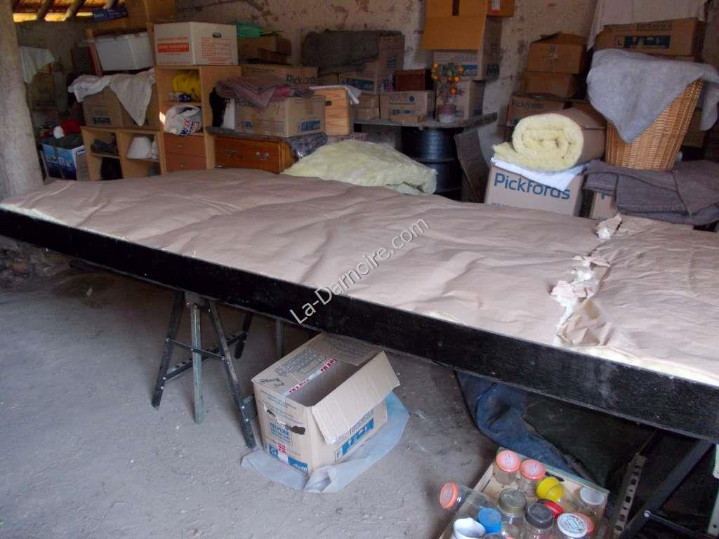
The second plywood panel was now used to provide some strips 100mm wide to form the sides of the solar thermal panel. Some laths (20mm x 20mm wooden strips) were added as bracing and the sides were glued and fixed with wood screws. All external surfaces were then painted with bituminous paint. Once this had dried, I used some glass fibre as insulation:
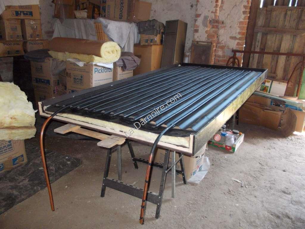
Using some thermal glue, I fixed a temperature sensor to the exit pipe. The wiring was temporarily taped to the exit pipe with insulation tape so that it did not get in the way during the journey onto the roof. The copper pipework was then painted matt black, and the entire thing was then placed into the wooden frame on top of the insulation.
Because the glass is in three panes, I had to install two wooden strips across the middle of the panel to support these. The wooden strips also had the effect of ensuring that there is an air-gap between the metal collector plate and the glass. This is important! Holes were drilled in the end piece of the frame to allow the pipework to exit; and the copper pipes were trimmed off so that they would be level with the base of the frame once the compression fittings were added. All joints were then sealed with mastic.
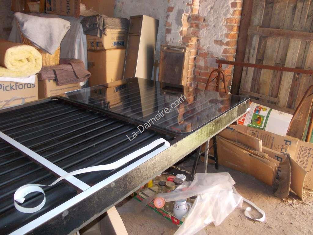
Now I had the unenviable task of cleaning both sides of three very dirty panes of glass before placing them on the panel! I used some 3mm closed-cell foam tape in order to ensure a water-tight seal between the glass and the wooden frame:
Some strips of scrap wood were then placed at the edges of the glass and screwed to the frame in order to keep the glass in place. These already had a 5mm rebate on one edge - which was fortuitously the thickness of the glass! Some silicone sealant was then placed as a bead around the edges of the glass, with the exception of the lowest edge. The glass is held in place here by a small piece of wood in the centre, retained by two screws (so that rainwater can run off the glass without pooling in the frame).
Installation
With the panel complete, the next Herculean task was to place it on the roof. I had already welded up a steel frame, and fixed this to the roof joists with Builders' Band. (This is an amazing item, useful for all sorts of things!)
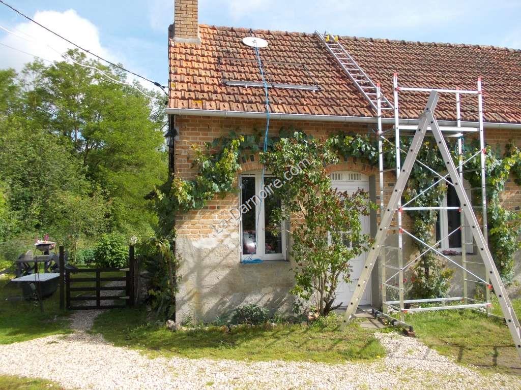
I fabricated a pulley using some scrap plywood, a plastic spool, and a steel bracket. This was placed above the panel's intended location...
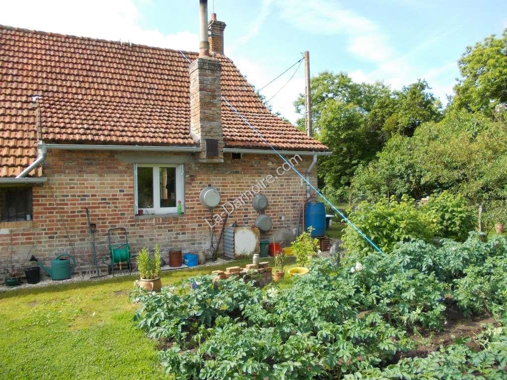
...and anchored (using a rope leading over the ridgeline to the other side of the house) with a long steel bar hammered into the vegetable garden like a tent-peg, between the rows of potatoes:
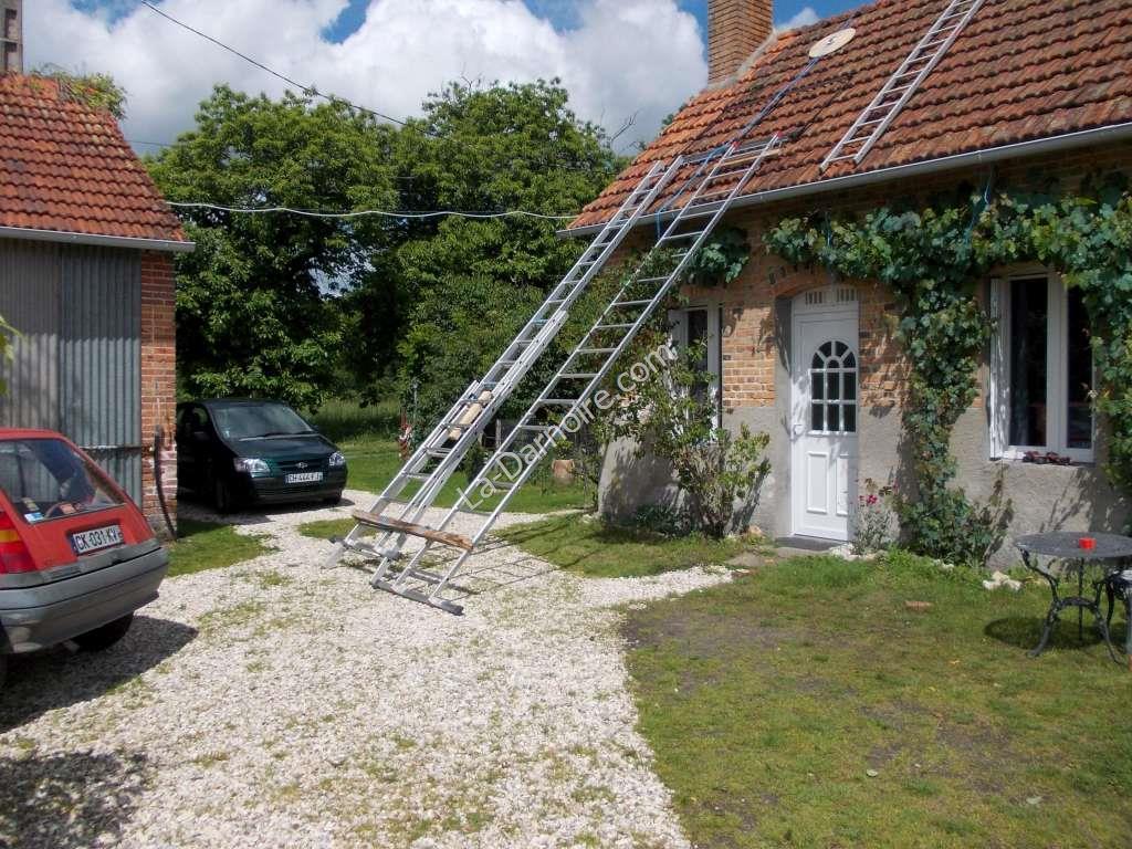
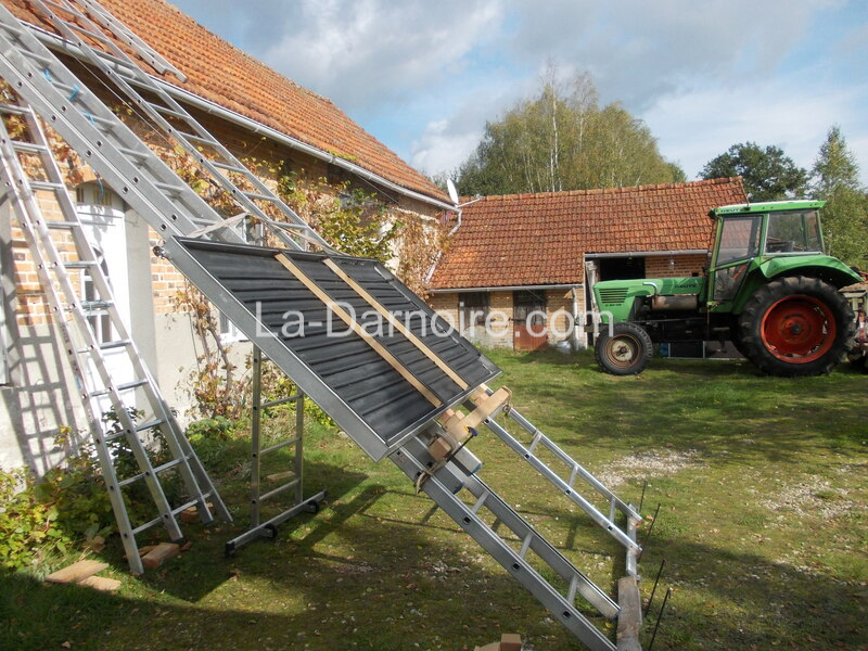
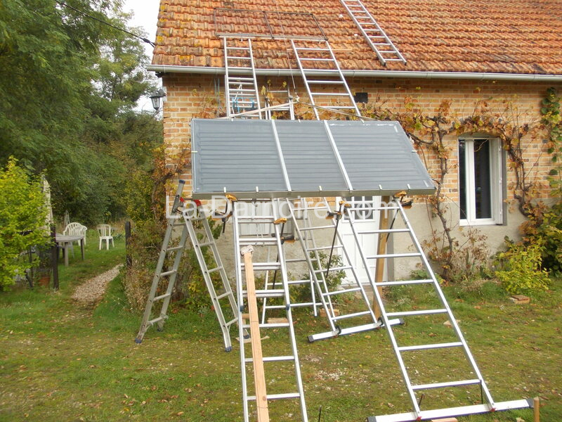
I then dismantled the scaffolding, and using the uprights (together with a long aluminium ladder) formed a ramp up which the solar panel was to be hoisted, with the aid of a rope around the home-made pulley.
The hoisting did not go smoothly. Due to the afternoon heat (which was when assistance from some neighbours was available), the bituminous paint on the underside of the panel stuck to the aluminium ladders. I should have greased them first. Other than that, the panel was finally in place with no damage other than some rope blisters, as I had forgotten to wear gloves.
Two holes were then drilled in the roof tiles using my smallest carborundum hole saw, and the copper pipes were connected to some PEX tubing, before the holes in the tiles were sealed with mastic and the pipes insulated.
UPDATE, 2022:
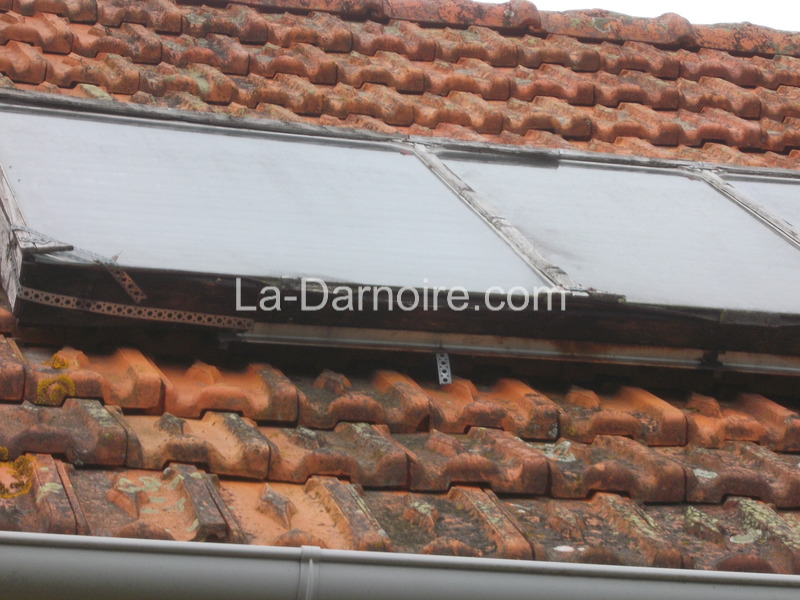
After over 7 years on the roof, the plywood frame was starting to look a bit worse for wear. The glass panels had started to slip downwards which necessitated some emergency reinforcing with builder's band. In spite of this, a small gap opened up at the top of the panel, allowing rainwater to enter.
It was obviously time for a new frame.
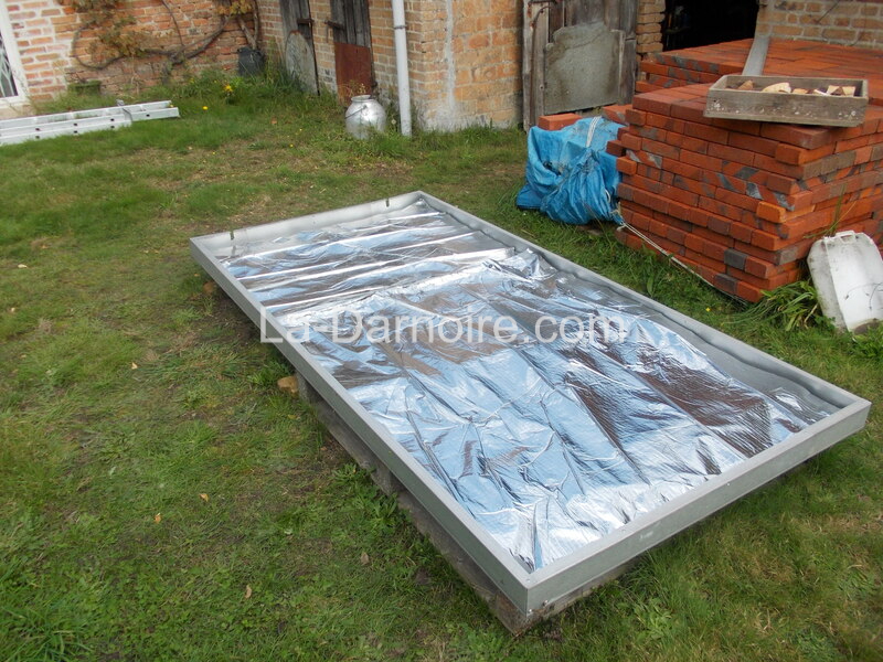
I therefore purchased a sheet of galvanized steel 2mm thick, the same size as the original plywood panel (1220x2440mm). A neighbour kindly donated some galvanized steel "U" channels 100mm wide, and I riveted these to the sheet. Some 14-layer polyethylene/foil insulation roll was then laid into the new frame.
The old panel was then drained, disconnected and dismantled in situ. The pipework and glass were still in good condition so were reused without any additional work being required apart from removing the old silicone sealant from the glass.
Once again I used ladders to slide the panel up onto the roof. But this time I used a hand winch which is mounted on the front bumper of the tractor. The panel was placed on the ladders prior to the glass being installed.
The glass was then installed on the new panel, and is held in place with galvanized angle brackets, riveted to the frame. Each of these brackets is cushioned from the glass with a small length of plastic tubing. A bead of silicone sealant was run around the edges of the glass.
The winch rope runs from the tractor to a pulley above the panel; this was attached to a rope running over the ridgeline of the roof, the same way as the panel was originally installed. However this time, with a proper pulley and the winch, it was possible to pull the panel up onto the roof single-handed, albeit very slowly!
Here's the new panel. It should last a lot longer than 7 years this time!
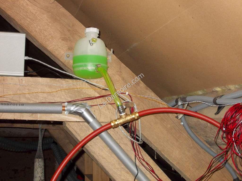
Inside the building, I used PEX tubing to connect the topmost exit of the panel to a car radiator expansion tank via a brass T-junction. This expansion tank was mounted at a slightly higher level than the solar panel, to allow air to exit the system. The PEX tube then connects to the upper connector of the heat exchanger (coils of copper pipe) in the thermal store.
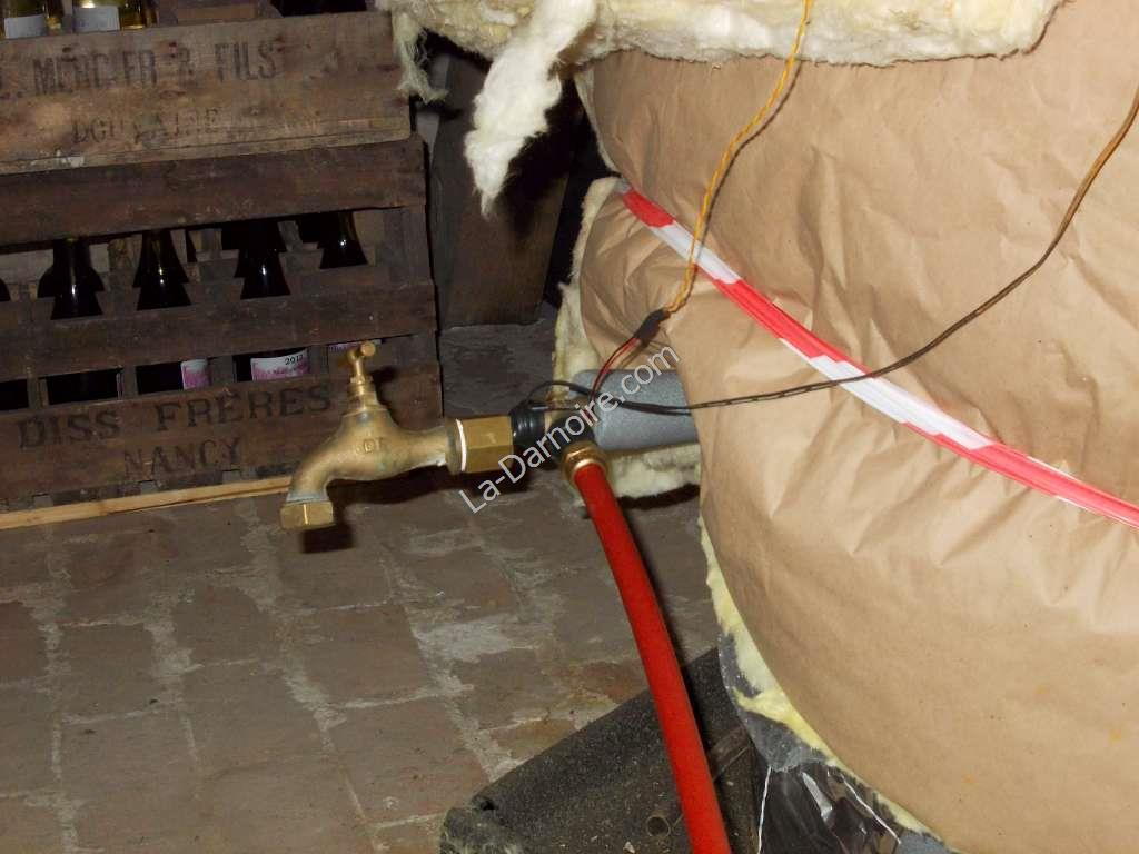
At the exit point of the thermal store I installed another T-junction connected to an ordinary garden tap (this is to allow the solar loop to be drained if necessary). Another length of PEX tube runs from this T-junction to the pump, which is a 12-volt Laing D5 Ecocirc with brass housing. From the pump a final length of PEX tubing completes the circuit at the lower end of the solar thermal panel.
Why is the pump 12 volts? So that a future photovoltaic panel can power the entire system; all the temperature gauges are 12 volts as well. And until such time as I install a PV panel, in an emergency situation (like a power cut), a vehicle battery can be connected to provide power to the pump so that the panel does not overheat. (See graph near the end of this page to see the panel temperatures with the pump switched off!)
Nearly 8 litres of antifreeze (propylene glycol) were then added to the circuit via the expansion tank. It took several hours and much stopping and starting of the pump before all the air was expelled from the system.
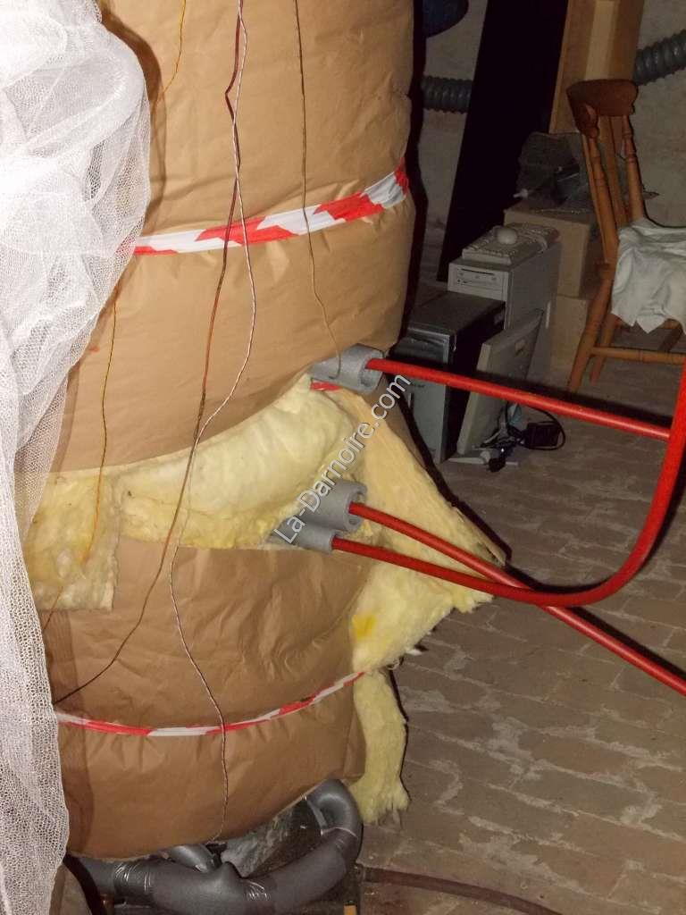
The lowest pipe in the photo above is the entry point for the solar heated water into the thermal store (the two pipes above it are for the radiator circuit). The solar return (and the tap for draining the system) can be seen in the next photo.
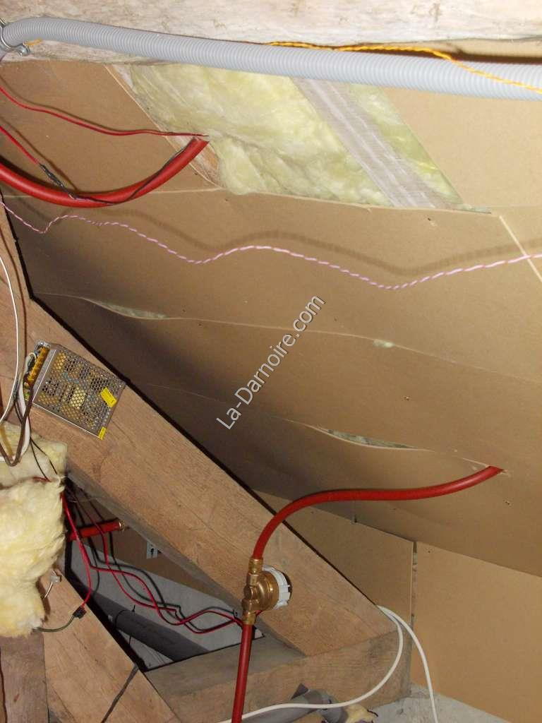
Finally in the photo above you can see the inside of the roof with the two pipes leading to the solar thermal panel. The pump is fixed to the wooden roof brace.
Control Panel
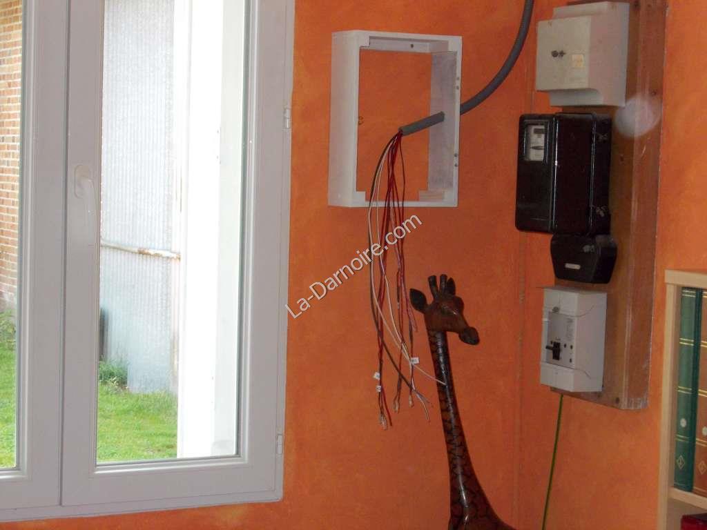
In order to be able to monitor the entire heating system, I decided to construct a control panel. Again using plywood, I made a simple frame and painted it white. A hole was drilled in one side to admit all the wiring from upstairs.
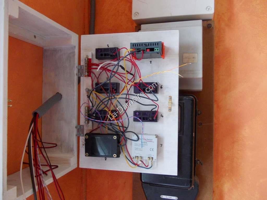
Here's the inside of the "lid". The thing at the top right is a thermostat which also shows the temperature at the top of the thermal store. If the temperature goes over 70°C the thermostat switches on the central heating pump; and the radiator in the bedroom becomes a "heat dump".
At the bottom right of the photo is a 12-volt timer; this also controls the central heating pump. (Which, in case you were wondering, is ALSO a 12V Laing D5 Ecocirc).
The unremarkable-looking black box at the bottom left is the brains of the entire solar circuit. It's a solar controller with relay which I obtained from REUK. It monitors the temperature difference between the panel and the thermal store; and controls the pump accordingly.
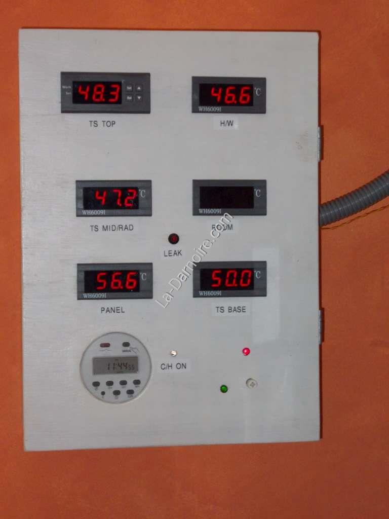
Finally, a photo of the operational panel (operational, that is, except for the middle right gauge which failed to display anything. Not serious; it's the temperature of the upstairs room):
Clockwise from top left: Temperature at the top of the thermal store
Temperature of hot water outlet
Non-working room temperature (replacement gauge on order)
Temperature at the bottom of the thermal store
Solar controller LED's. The red LED indicates the panel pump is operational; the green LED indicates the panel is hotter than the thermal store.
Timer for central heating circuit
Temperature of solar thermal panel
Temperature of middle of thermal store
The little LED in the centre of the panel flashes red if any water is present in the tray of the thermal store so that action can be taken! You can read about our little problem with a leak here.
Results
So, does it work?
Yes.
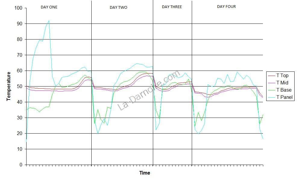
I did consider temperature probes which sent readings wirelessly to a data-logger so that fancy graphs could be constructed, but decided against it. Instead, I created a spreadsheet and entered readings every hour or so (during the day only!) and created a fancy graph from that instead:
(Note: The blue line indicating the solar thermal panel temperature crosses the 50° line at around 10:30. On day one, readings were taken from 09:00. I stopped taking temperature recordings at around 18:00, and started at 06:30 on each of the remaining three days. The X-axis (time) is not to scale.)
On the first day, when the solar loop was filled and the pump switched on for the first time, there was not a cloud to be seen. Due to air in the pipework, and the stopping and starting of the pump, the panel temperature hit a massive 92°C.
Day two was another cloudless day; and results were near-perfect. The temperature at the top of the thermal store peaked at 58.3°C, so the bathwater required the addition of some cold water! I stopped taking readings after that, until 06:30 the following morning.
Day three: only partly sunny. You can see the blue line for the solar panel demonstrating the temperature fluctuations. The bathwater temperature was still hot enough.
Day four: an even cloudier day. But for the fourth day in a row we have not needed to light the boiler stove to heat water for a wash.
So there you have it. If we have constant cloud cover, the solar thermal panel is not able to heat the water sufficiently; but then we just light the boiler stove for an hour. The boiler stove is also our source of heating during winter, together with the kitchen range, of course.
I had considered installing a third water-heating option; namely an instantaneous gas water heater (which would only heat the water if it was below a certain temperature - for example after a cloudy week during the summer). But I think we'll shelve the plans for this for a while, and see how we get on with the current installation over the course of a year or so.
Costs
So, how much did this system cost?
Here's a breakdown of prices paid (all converted to UK £) as at June 2014:
| Plywood sheet x 1.5 | 33.33 |
| Aluminium panels | 0.00 |
| 5mm safety glass | 0.00 |
| Glass fibre 100mm | 6.44 |
| Copper pipe 40m | 183.82 |
| All brass pipe fittings | 37.83 |
| PEX tube | 2.59 |
| Laing D5 pump | 95.90 |
| Temperature gauges and probes | 47.50 |
| Solar controller | 29.78 |
| Thermal glue | 2.94 |
| Thermostat | 9.13 |
| Wiring for probes | 12.87 |
| 12V transformer | 11.18 |
| Expansion tank | 11.50 |
| Pipe insulation | 0.41 |
| Grand Total | £485.21 |
|---|
And finally, a rough calculation of how much power the panel produces.
It takes 4180 Joules of energy to heat 1 litre of water by 1° C.
Taking an average temperature of the entire thermal store, on a sunny day over a period of 11 hours the heat gain was 14.9°C.
The tank contains approximately 470 litres of water.
So, 470 litres water x 14.9° x 4180 = 29,272,540 Joules.
One Watt is 1 Joule per second.
11 hours contain 39,600 seconds.
So 29272540 / 39600 = 740 Watts.
Therefore on a sunny day, over 11 hours, that's the equivalent of 8.14kWh of free energy.
Well I did say it was a rough calculation!
